This page describes the special features of the ESP8266 (ESP) Arduino client. Please read the general help first and in particular setup help.
The monitor period for a device is the number of seconds between monitor/actuation cycles. For ESP clients, the active period is the number seconds that the device is not deep sleeping. In stateless monitoring applications an ESP client can wake up from a deep sleep, measure inputs and go straight back go back to deep sleep. An active period is required however when actuating pins or handling interrupts. If the active period equals the monitor period then the device never enters deep sleep.
If you plan to utilize the ESP's deep sleep feature, you must connect GPIO pin 16 to the RST pin. This ensures that the wake-up signal on GPIO 16 resets the device. If you fail to do so the ESP will never return from its first deep sleep.
GPIO pin 0 must be pulled HIGH upon restart to ensure that the ESP boots normally. Do so by inserting a 10 kOhm resistor between GPIO pin 0 and the 3.3V pin. Since GPIO pin 0 is also the default alarm pin (described later), this also ensures that the alarm is off upon reboot.
NB: If GPIO pin 0 is LOW during reboot and GPIO pins 2 and 15 are left as is (i.e., pulled HIGH and LOW respectively) the ESP will enter boot loader mode and the red LED will be dimly illuminated. The red LED may also be dimly illuminated when GPIO pin 0 is left to float, i.e., is neither LOW nor HIGH.
By default, the ESP Arduino client uses the blue LED (GPIO pin 2) to signal various conditions as follows:
The ESP Arduino client implements a number of variables which are used to control pulse mode and alarm mode described below. As for configuration data, variables are saved to the EEPROM. Therefore once configured, the functions these variables control do not require network connectivity to operate. Note that variable names are case sensitive.
| Variable | Description |
|---|---|
| Pulses | # of pulses (required for pulse mode). |
| PulseWidth | Pulse width in seconds (required for pulse mode). |
| PulseCycle | Cycle (repeat) period in seconds (monitor period by default). |
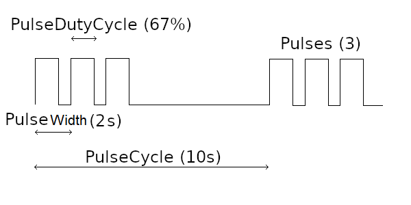
| PulseDutyCycle | Pulse duty cycle (50% by default). A pulse width of 2s and a duty cycle of 50% means the pulse is on for 1s and off for 1s. |
| AlarmPin | GPIO pin to drive during an alarm (GPIO 0 by default). |
| AlarmLevel | Logical level during alarm condition (LOW by default). |
| AlarmPeriod | Alarm period for network alarms, or 0 for continuous alarm (seconds). |
| AlarmNetwork | Raise alarm when the number of network failures exceeds this number (0 to disable). |
| AlarmVoltage | Raise alarm when the analog (A0) value drops below this value (number between 1 and 1023, or 0 to disable). |
| AlarmRecoveryVoltage | Clear the voltage alarm when the analog (A0) value exceeds this value (number between 1 and 1023, or 0 to use the AlarmVoltage). |
| PeakVoltage | The analog (A0) value corresponding to a fully-charged battery, used to clamp values for AlarmVoltage and AlarmRecoveryVoltage (defaults to 845). |
| AutoRestart | Restart device if the alarm continues for too long (minutes). |
| SensePin | GPIO pin that is driven HIGH while sensing pins, otherwise held LOW. Used to drive a relay which regulates power to one or more sensors or a voltage divider (0 to disable). |
Pulse mode enables the ESP Arduino client to drive the blue LED and GPIO pin 2. The shape of the pulse is controlled by the Pulses, PulseWidth, PulseCycle and PulseDutyCycle variables as shown in the diagram below.
Pulse mode can be temporarily suppressed by actuating the X14 custom pin. When X14 is present and true, the pulse is suppressed. X14 is not stored in EEPROM to avoid permanently suppressing the pulse due to loss of network. To permanently disable pulsing, either delete the Pulses and PulseWidth variables or set them to zero.
Alarm mode enables the ESP Arduino client to drive a specified GPIO pin whenever the number of consecutive network failures exceeds a given threshold (AlarmNetwork) or the analog (A0) value drops below a given value (AlarmVoltage). Since the default AlarmPin is GPIO pin 0 and the default AlarmLevel is LOW, this means the ESP's red LED will be lit whenever there is an alarm. The alarm pin is typically connected to a power supply relay in order to power cycle network equipment (for AlarmPeriod seconds).
A network alarm is raised whenever the number of consecutive network failures exceeds the threshold specified by AlarmNetwork. This alarm is active only for AlarmPeriod seconds, and is intended to be used to reset network equipment.
The voltage alarm is intended to prevent a battery-powered system from completely losing power. Whereas network alarms are transient (i.e., for AlarmPeriod seconds), voltage alarms persist until the voltage recovers (i.e., exceeds AlarmRecoveryVoltage). Therefore if the voltage alarm is used to turn off power to network equipment, the ESP will be disconnected from the network until the alarm is cleared. If AlarmRecoveryVoltage is not specified, it defaults to AlarmVoltage.
Despite their names, AlarmVoltage and AlarmRecoveryVoltage are analog (A0) values, not voltages. This is because NetReceiver sensors convert analog values to a voltages, not NetSender. To find suitable analog values first include X10 in the input pin list. This reports the current analog (A0) value. A value of -1 means the device is not configured and the voltage check is disabled. If this is the case, first set AlarmVoltage to 1 (the smallest possible value that enables voltage checking) then update the device. The voltage scale is found by dividing the analog value by the measured voltage. For example, if the current battery voltage is 25.0V and the analog value is 856, the conversion scale is 34.24 (=856/25). Use the scale to calculate appropriate values for AlarmVoltage and AlarmRecoveryVoltage (examples shown below).
To avoid accidentally setting AlarmVoltage or AlarmRecoveyVoltage too high and causing the ESP to remain in alarm mode, AlarmVoltage and AlarmRecoveyVoltage cannot exceed PeakVoltage. It is therefore important to set PeakVoltage before enabling voltage alarm mode, i.e., by setting a non-zero value for AlarmVoltage. To do this, disconnect the charger once the battery is fully charged, then measure the A0 value.
NB: The PeakVoltage is not the maximum possible voltage, as higher voltages will be experienced during charging. This is desirable as it means that a voltage alarm can be canceled by simply charging the ESP sufficiently long.
| Description | Analog value | Voltage (24V system) |
|---|---|---|
| PeakVoltage | 877 | 25.6 V |
| Current voltage | 856 | 25.0 V |
| AlarmRecoveryVoltage | 835 | 24.4 V |
| AlarmVoltage | 822 | 24.0 V |
NB: A typical lead-acid battery that is fully-charged at 12.8V will be 50% charged at 12.2V, and completely discharged at 11.6V. Don't wait till then!
A timer is started whenever an alarm first occurs. If the alarm condition persists for more than AutoRestart minutes, the ESP is automatically restarted and the alarm is reset. If the alarm condition is still present however, the ESP will re-alarm itself and the timer will start over again.
Clicking on the 'Alarm' button for the selected device, forces a transient alarm for AlarmPeriod seconds without restarting the ESP. Note the following:
Alternatively, the alarm pin can be actuated just like any other GPIO pin. For example, to control the default alarm pin of GPIO pin 0 include D0 in the outputs. Writing LOW (AlarmLevel) to D0 start the alarm timer and writing HIGH (!AlarmLevel) will stop it.
NB: The ESP will lose connectivity if the alarm results in network equipment being powered down. Ensure that AutoRestart is set, otherwise the ESP will remain permanently offline.
The X13 custom pin reports the reason why the ESP last rebooted, as follows:
The ESP client writes serial output at 115200 Baud. When the device is unconfigured it outputs the NetSender version followed the device's MAC address at the start of each cycle. Once the device is configured it runs silently, unless put into debug mode. Updating the device returns the device to normal mode.
 Home
Home Sites
Sites Monitor
 Settings
 Admin
Admin Help
Help